Offensive Development in Assembly and C: Introduction to Assembly

Overview
This series will focus on Malware/Payload development in Assembly and C for offensive security. I will be using Assembly language and C as required. The idea is to not be dependent on any language but to be able to use the capabilities of the language as required to complete the task. I will try to cover the important and required aspects of assembly that we need to get started with our development. Whenever I say assembly, I will be referring to 64 bit assembly (runs on 64 bit architecture) code not 32 bit assembly (can run on 64 bit and 32 bit architecture) code only.
Contents
- Setting up the environment
- Things to remember
- Getting a basic idea of assembly
- Fundamental data types
- Internal architecture
- General purpose registers
- RFLAGS register
- RIP Register
- Instruction Set
- Memory addressing
- Endianness
Setting up the environment
To begin coding we first need to setup our environment. What do we need:
- Windows 11 Operating system
- Windows SDK
- Visual Studio Code
I myself have windows 11 installed on my system but for people who don’t, you will need to install Windows 11 on your virtual machine (Virtual Box or VMWare Player/Workstation). A copy of Windows 11 can be downloaded from this link. This will give you the Windows 11 enterprise version which is valid for 90 days. After downloading simply install it as a Virtual Machine. You can find many tutorials for that on YouTube.
After installing the Windows OS, update the operating system if required. Then we need the Windows SDK which can be downloaded from this link. The Windows SDK should provide you with the ml64.exe (Microsoft Macro Assembler) MASM assembler that we need for assembling our assembly code. It will also install the cl.exe (Microsoft C++ MSVC C and C++ compiler and linker) which is required to compile the C code. WinDbg will also come along the SDK as we can use it for debugging later on if required.
After the SDK, we need an editor. I have chosen Visual Studio Code. It has extensions that help in highlighting the assembly code better.
After everything is installed, make sure to take a snapshot of the machine if you are using Virtual Machine.
Things to remember
This article has skipped over things that may not make sense and cause confusion to focus on what’s needed for the time being. But I will point out the details of instructions and their meaning when used in code. But I do suggest to start reading the Intel manuals after reading this article. Intel manuals Volume1 and Volume 2 (2A, 2B, 2C, 2D) have everything that we need. Volume 1 contains an overview and information about the Intel architecture and Volume 2 goes in-depth about the instruction format and types of instructions. You can download the manuals from this link.
Getting a basic idea of assembly
We won’t going deep into Computer Architecture here as that is not needed and out of scope but some basic things need to be understood. So lets look at what assembly code is.
The CPU understands machine language. Machine language although seems random to us has a particular format. This format is what helps the CPU understand how long an instruction is, what the instruction need to do and so on. Below is the instruction format of x64 architecture. The x64 architecture is formally called “Intel 64” by Intel.
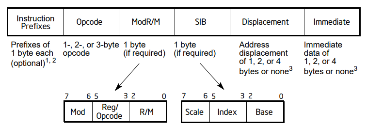
Below are 2 examples of how an instruction is represented in machine code based on the instruction format.
Machine Code                Instruction
B8 01 00 00 00              mov eax, 1

B8 - Opcode for the mov instruction
01 00 00 00 00 - The immediate value 1 represented in little-endian hexadecimal format

Machine Code                Instruction
0F B6 84 4B 40 E2 01 00     movzx eax, byte ptr [ebx+ecx*2+123456]

0F B6 - Opcode for movzx instruction
84 - ModR/M byte that specifies the source operand (a byte in memory) and a destination operand (eax)
4B - This is the SIB (Scale-Index-Base) byte that specifies the scale factor (2), the index register (ecx), and the base register (ebx)
40 E2 01 00 -  The displacement 123456 represented in little-endian hexadecimal format
Since we are not concerned with manipulating machine instructions like a Gigachad hacker at the moment, its ok not to understand the above completely. But keep in mind the overall idea.
The instruction format is what dictates how the CPU interprets the machine code. When we write assembly code i.e. mov rax, rbx. This instruction is converted to appropriate machine level instruction by the assembler based on the instruction format. In the example (mov rax, rbx), mov is called a mnemonic. rax and rbx are called operands. rax is the 1st operand (destination) and rbx is the 2nd operand (source). The mov instruction moves data from the 2nd operand to the 1st operand. The data is moved from the second to the first operand. This is very important to remember when writing assembly for windows assembler which uses the Intel syntax. On Linux the tool chain defaults to the AT&T syntax in which the data would be moved from the 1st operand to the 2nd operand.
Fundamental data types
Fundamental data types represent the unit of data that is seen and manipulated by the processor. Below are the fundamental data types as seen by the CPU.
| Data Type | Size | Usage |
| Byte | 8 | Characters, small integers |
| Word | 16 | Wide characters, integers |
| Doubleword | 32 | Integers, single-precision floating point |
| Quadword | 64 | Integers, double-precision floating point |
| Double Quadword | 128 | Packed integers, packed floating point |
Weather the data is interpreted as integer, float will depend on the instruction mnemonic. Below is an example
mov rax, 123456789                        ; moves 64 bit integer value into rax

movsd xmm0, qword ptr [rbp-8]             ; mov 64 bit double precision floating point value to xmm0
Internal architecture
From the point of view of program that is executing the components that are important to us are the registers, status and control flags. Below is a diagram that shows the various components.
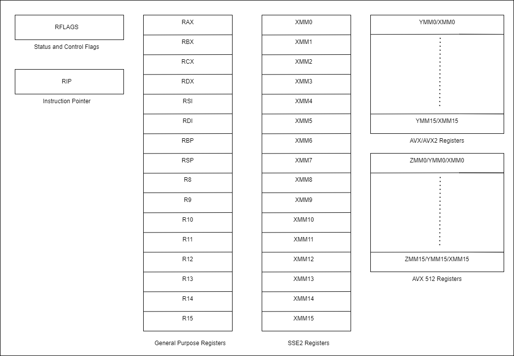
Note: We do not need the XMM, YMM and ZMM registers along with Floating point status and control for our work. XMM, YMM and ZMM registers are mostly used in operations that require speed as multiple data units can be packed in an array and used for data manipulation.
General purpose registers
x64 architecture has 16 general purpose registers namely RAX, RBX, RCX, RDX, RSI, RDI, RBP, RSP, R8, R9, R10, R11, R12, R13, R14, R15 all of which are 64 bits in size. They are called General Purpose Registers as they can be used in various different operations like data manipulation, data storage, address manipulation and storage etc. The image below show the registers and the low order bytes.
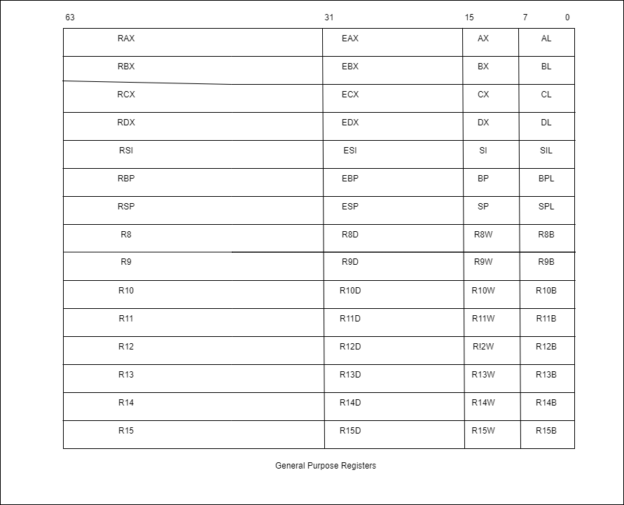
The low order bytes can be accessed separately i.e. mov eax, edx or mov ax, dx. For RAX register, AL represents the lowest 8 bits (Byte), AX represents the lowest 16 bits (Word), EAX represents the lowest 32 bit (Double Word). All of the above data units can be accessed separately.
Note: The high order 8 bits of the registers AX, BX, CX, DX can be accessed separately as AH, BH, CH, DH respectively.
RFLAGS register
The RFLAGS register is also known as the status and control register as it stores the status of the CPU after the execution of any instruction. Although it is 64 bits in size bits 22 to 63 are reserved. Suppose we execute an instruction like sub rax, 10. This instruction subtracts 10 from the value that is stored in the RAX register. If the resulting value is a 0 then the ZF (Zero flag) will be set to 1, which we can use to decide what the code should do next.
Below is an image from the Intel manual showing all the bits and their meaning. Each flag can take up to one bit or multiple bits of space.
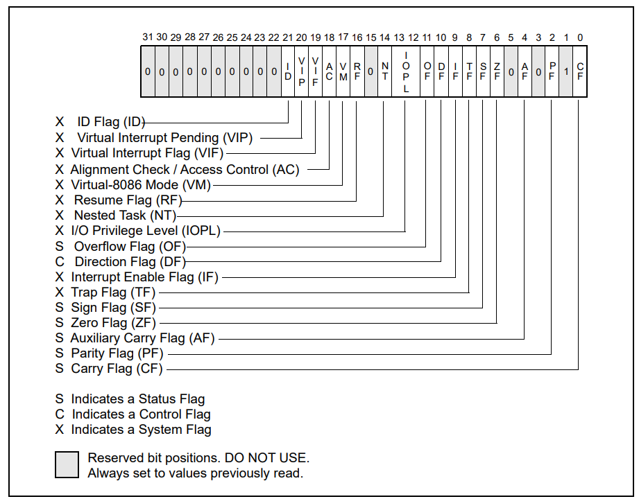
We only care about the status flags for now and will learn about them as we use them. I encourage you to read more about them in the Intel manual.
| CF | Carry Flag |
| PF | Parity Flag |
| ZF | Zero Flag |
| SF | Sign Flag |
| OF | Overflow Flag |
Out of the above the most important to remember is the ZF (Zero Flag). This is what is checked whenever we use instructions like je (jump if equal), jz(jump if zero). Below is an example to show how it is used.
mov rax, rdx
mov rcx, 6              ; rcx initialized to 6

LABEL1:
xor rax, 2              ; xor value in rax with 2
dec rcx                 ; decrement rcx by 1
je DONE                 ; check if ZF flag was set after the previous operation and jump to label DONE if ZF is set
jmp LABEL1              ; else direct jump to LABEL1

DONE:
ret                     ; return from function
RIP Register
RIP register also called the instruction pointer register is very important as it contains the address of the next instruction to be executed. The contents of the RIP register cannot be altered directly. When there is a branching instruction i.e. an instruction that leads the code to jump to some other address, the RIP register is altered automatically. The jmp(Jump) and jcc(Jump if condition is true) instructions alter the rip without leading to the modification of the stack. The call and ret instruction lead to changes in the stack. This is important to consider because if we want to find the address of particular data or instruction in our code, we first need some address inside our code which we can increment or decrement and check for the data/instruction that we are looking for at the address.
mov rax, 10
call LABEL1

LABEL1:
pop rcx
In the above code example we first use the call instruction to make the CPU go the LABEL1 address. When the call instruction is executed the CPU pushes the address of the next instruction on the stack in order to return to that point after the function(in our case no function) is executed. So we use the pop rcx instruction which will take the address that was pushed by CPU and put it in the rcx register. Now we have the address of our code and therefore we can increment the address and hunt for a specific mnemonic (opcode)/ data value. We do not need to have a ret instruction as the value pushed on to the stack has been removed and stored in the rcx register after the pop rcx instruction was executed.
Instruction Set
An instruction set, also known as an instruction set architecture (ISA), is a set of commands that a processor can understand and execute. These instructions tell the processor what operations to perform, such as arithmetic, data manipulation, memory related operations etc.
The instruction set is a fundamental architectural component of a CPU and is either built into the CPU or into microcode, a layer between the instruction set (assembly code) and the hardware circuitry. When we talk about Intel or AMD we are dealing with a CISC (Complex Instruction Set Computer). In CISC the instruction size is not fixed, this allows the CPU to perform complex operations but the cost is, it can take multiple CPU cycles to complete one instruction. On the other hand ARM based processors use RISC (Reduced Instruction Set Computer) in which each instruction has a fixed size.
Below are some of the most common instruction. For an exhaustive list and their complete description refer to the Intel manual.
| Mnemonic | Instruction |
| add | Integer addition |
| call | Call procedure |
| cld | Clear direction flag (RFLAGS.DF) |
| cmovcc | Conditional move |
| cmp | Compare operands |
| cpuid | CPU identification and feature info |
| dec | Decrement operand by 1 |
| div | Unsigned integer division |
| idiv | Signed integer division |
| imul | Signed integer multiplication |
| mul | Unsigned integer multiplication |
| inc | Increment operand by 1 |
| jcc | Conditional jump |
| jmp | Unconditional jump |
| lea | Load effective address |
| mov | Move data |
| movsx | Move integer with sign extension |
| movsxd | Move integer with sign extension |
| movzx | Move integer with zero extension |
| neg | Two’s complement negation |
| not | One’s complement negation |
| or | Bitwise inclusive OR |
| xor | Bitwise exclusive OR |
| and | Bitwise AND |
| pop | Pop value at stack top to operand |
| popfq | Pop value at stack top to RFLAGS |
| push | Push operand to stack |
| pushfq | Push RFLAGS to stack |
| ret | Return from procedure |
| rep | Repeat string operation (prefix) |
| reppe | Repeat string operation (prefix) |
| reppz | Repeat string operation (prefix) |
| repne | Repeat string operation (prefix) |
| repnz | Repeat string operation (prefix) |
| rol | Rotate left |
| ror | Rotate right |
| sar | Shift arithmetic right |
| setcc | Set byte on condition |
| shl | Shift logical left |
| shr | Shift logical right |
| std | Set direction flag |
| stosb | Store string value byte |
| stosw | Store string value word |
| stosd | Store string value doubleword |
| stosq | Store string value quadword |
| test | Test operand (set status flag) |
| xchg | Exchange source & destination operand values |
Memory addressing
Whenever we want to access data in memory we need to follow a particular format. The instruction used should have the format as below
EffectiveAddress = BaseRegister + IndexRegister * ScaleFactor + Displacement
EffectiveAddress refers to the final address that will be accessed. There are four components that are mentioned above i.e. BaseRegister, IndexRegister, ScaleFactor, Displacement. It is not required to use all the components and depends on what we are trying to access - a value in an array, a value inside a structure etc.
| Example | Addressing Form |
| mov rax, qword ptr [rbx] | BaseRegister |
| mov rax, qword ptr [rbx + rcx] | BaseRegister + IndexRegister |
| mov rax, qword ptr [rbx + rcx + 2] | BaseRegister + IndexRegister + Displacement |
| mov rax, qword ptr [rbx + rcx * 4 + 2] | BaseRegister + IndexRegister * ScaleFactor + Displacement |
| mov eax, dword ptr [Variable1] | RIP + Displacement (Relative addressing) |
Note: The IndexRegister cannot be RSP. The ScaleFactor can be 2, 4, 8. The Displacement has to be 32 bit value.
The last example mov rax, dword ptr[Variable1] is called relative addressing. Whenever we use instruction like this the machine code includes an offset to the Variable1. This offset is added to the address of the next instruction (stored in the RIP). The final address is from where the value of the Variable1 is retrieved. This is important to remember when writing position independent code.
Endianness
Whenever data is stored in memory it is stored in little-endian format. Both Intel and AMD use little-endian byte order in their x86 and x64 architecture. In little-endian the least significant byte of a multi-byte value is stored in the lowest address and the most significant byte is stored in the highest address.
Consider the below code that declares 4 variables of 1 byte, 2 byte, 4 byte and 8 byte size inside the data section.
.DATA
    byteValue           db  1Ah
    wordValue           dw  1A2Ah
    dwordValue          dd  1A2A3A4Ah
    qwordValue          dq  1A2A3A4A5A6A7A8Ah

.CODE
    mov al, byte ptr[byteValue]                 ; loads the value 1Ah in al
    mov bx, word ptr[wordValue]                 ; loads the value 1A2Ah in cx
    mov ecx, dword ptr[dwordValue]              ; loads the value 1A2A3A4Ah in ecx
    mov rcx, qword ptr[qwordValue]              ; loads the value 1A2A3A4A5A6A7A8Ah in rcx
The diagram below shows how the values will be stored in memory in the .DATA section when the file is loaded in memory.
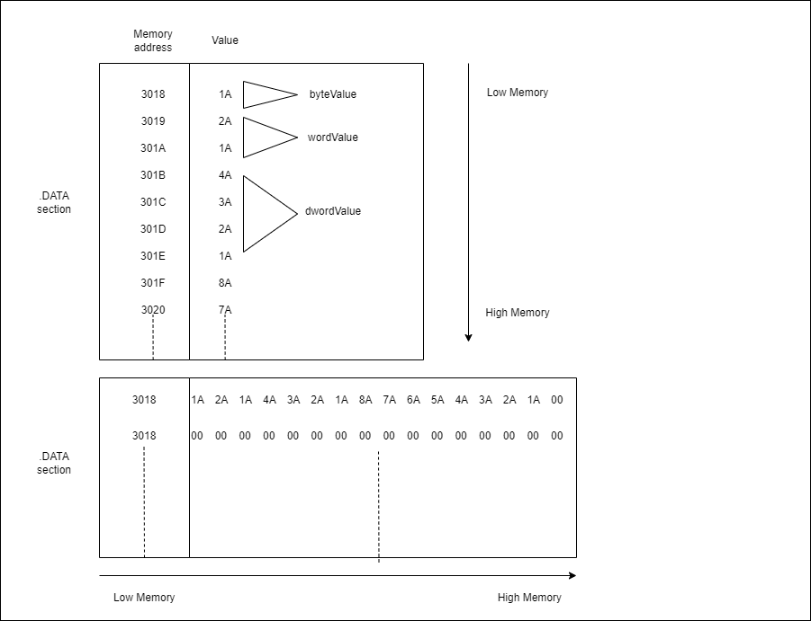
As we can see, the least significant byte of of the values whose size is more than a byte is stored in the lowest address and the most significant byte is stored in the highest address. Whenever we retrieve the value from an address we don’t have to worry about endianness since the CPU takes care of it. But there is a particular case we need to be aware of when we try to use stack strings i.e when we try to store a string in a register and try to move it to stack like below.
sub rsp, 24
mov rax, 6365746F7270746Eh                        ; ntprotectvirtualmemory -> 6E 74 70 72 6F 74 65 63 74 76 69 72 74 75 61 6C 6D 65 6D 6F 72 79
mov qword ptr[rsp], rax
mov rax, 6C61757472697674h
mov qword ptr[rsp + 8], rax
mov rax, 000079726F6D656Dh
mov qword ptr[rsp + 16], rax
In the above scenario, we are storing the string in reverse order. So when the value is moved to the stack the lowest byte will be stored first i.e. the first character of our string and then the next and so on.
Endianness is something that may be hard to grasp at first and also cause confusion but with enough looking at data in memory, it will make sense eventually.